ad_ul_data_logger_rj45
Table of Contents
I/O Connector
Description
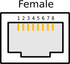
Board use RJ45 connector to provide connection to follow function
- Power line +5V, GND
- Serial port Rx, Tx (digital line D0 and D1)
- TWI interface SDA, SCL (depends of version Uno Analogue Line A4,A5, Leonardo Digital Line D2, D3)
- Analogue Line A6,A7 (use from special models or may be reconected to other Analogue Line)
- Digital Line D8,D9,D4,D6
Used Pins
Arduino Leonardo Compatibility
Arduino Uno Compatibility
Arduino Due Compatibility
Digital Pin: 0, 1, 4, 6, 8, 9
Analogue Pin: special (6, 7)
Bus: TWI
Power Pin: GND, +5V
Config options
- Analogue A6
- Power +5V
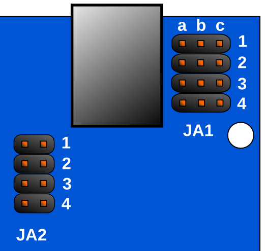
- SP Rx/D0 or D8 depends of JA1 4 row (a-b D8, b-c Rx/D0)
- SP Tx/D1 or D9 depends of JA1 3 row (a-b D9, b-c Tx/D1)
- Power GND
- Digital D4
- TWI SDA (Uno A4/Leo D2) or D6 depends of JA1 2 row (a-b D6, b-c A4/D2)
- TWI SCL (Uno A5/Leo D3) or A7 depends of JA1 1 row (a-b A7, b-c A5/D3)
PullUp Jumper Array JA2
If shorten each row connect PullUp resistor of 4K7 from +5V to corespondence line.
- D4
- line from pin 7 of RJ45 connector (see up for value)
- line from pin 4 of RJ45 connector (see up for value)
- line from pin 3 of RJ45 connector (see up for value)
ad_ul_data_logger_rj45.txt · Last modified: by 127.0.0.1


