data_logger_errled
Table of Contents
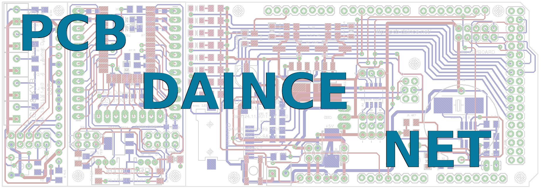
Data Logger PCB
Error LED
Description
Maximum 8 Digital Pin in OUTPUT mode are used for serial connected LEDs (one is always on).
Used Pins
Digital Output Pin: 30, 32, 34, 36, 38, 40, 42, 44
Power Pin: GND, +5V (see supported function)

Example
- ErrorLED_DL_V1_0_0.pde
/* Error LED example

   Board: DATA LOGER ARDUINO MEGA SHIELD, 24.11.2011, V 1.0.0
   Author: Dubravko Penezić 2011, Creative Commons BY-NC-SA

   Used pins:
     DOP-30, DOP-32, DOP-34, DOP-36, DOP-38, DOP-40, DOP-42, DOP-44

   State definition:
     LOW - green LED
     HIGH - red LED
 */

// set pins array
const int errorLED[] = {30, 32, 34, 36, 38, 40, 42, 44};
// set number of pins
const int noErrorLED = 8;

// init
void setup() {
  setErrorLED();
}

// loop
void loop() {
  int i;
  // All errorLED activate
  for (i = 0; i < noErrorLED; i = i + 1) {
    setError(i);
    delay(3000);
  }

  delay(10000);

  // All errorLED deactivate
  for (i = 0; i < noErrorLED; i = i + 1) {
    setOK(i);
    delay(3000);
  }

  delay(10000);
  // Alternate errorLED
    for (i = 0; i < noErrorLED; i = i + 1) {
    setError(i);
    delay(2000);
    setOK(i);
    delay(3000);
  }

}


// set all digital pins to output mode, and state LOW (green light)
void setErrorLED() {
  int i;
  for (i = 0; i < noErrorLED; i = i + 1) {
    pinMode(errorLED[i], OUTPUT);
    digitalWrite(errorLED[i], LOW);
  }
}

//set errorLED to ON (red light)
void setError(int no) {
  if(no > -1 & no < noErrorLED) {
    digitalWrite(errorLED[no], HIGH);
  }
}

//set errorLED to OFF (green light)
void setOK(int no) {
  if(no > -1 & no < noErrorLED) {
    digitalWrite(errorLED[no], LOW);
  }
}
Also you may use Arduino library DpLEDError available from here.
data_logger_errled.txt · Last modified: by 127.0.0.1